This page is being worked on March 2019
This module measurement method uses the variable of resistance to determine the power IV curve. By changing the resistance of the module load and measuring voltage and current, the power IV curve can be generated for a specific panel. This method will ultimately allow the user of the module to compare and contrast the factory curves provided for that module. A power IV curve can provide the maximum power point (PMAX) of the module, which can be contrasted with the manufacturer’s specifications of the expected power output. Because there is a power IV curve, this method can also help identify shunt and series resistance in a module. A discussion of the effects of resistance on a solar module can be found here.
Measuring with a Load
Ideally, we want to operate the module at the maximum power point. The module voltage is VMP and the module current is IMP. We already know the power output of the module PMAX but we also need the load resistance, Rload, which is found from ohms law:
$$R_{load} = \frac{V_{MP}}{I_{MP}} $$
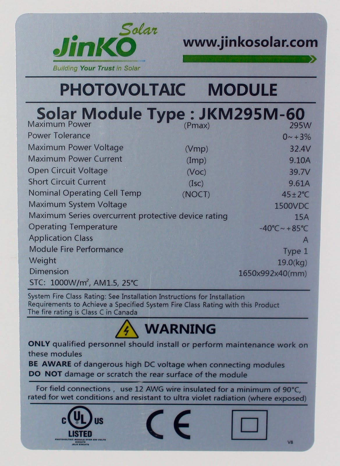
In the case of the module below, where VMP equals 32.4 V and IMP equals 9.1 A, Rload should be 3.5 ohms.

The resistors used should be around the maximum power voltage (Vmp) and the maximum power current (Imp). If the Vmp and Imp are not known, open circuit voltage (Voc) and short circuit current (Isc) is a good approximation. Usually, the back of the module will have a label listing VMP and the IMP. The VOC and ISC can be found using a multimeter.
Modules produce hundreds of watts or power so high wattage power resistors are needed. However, the measurements are only for short periods so we don’t need power resistors of the full power rating. Cooling the resistors with water also helps. The ones used in the example results were designed to withstand 100 Watts and varied between 0.5 Ω, 1 Ω, and 4 Ω. When connected in various series combinations, the resistance ranged from 1 Ω to 19 Ω. About a fifth to five times the calculated resistance at PMAX calculated above.

Materials needed
- Two Multimeters - One for voltage and one for current
- Water to cool the resistors
- Two or more alligator clip cords
- Protective gloves - modules and resistors get hot
- Resistors
- Solar Module

The schematic for placing the meters is shown below. The resistors heat up during the measurement and their value will likely drift. Having two meters, one for current and one for voltage means that we do not need precision resistors or have to the uncertainty of drift during the measurement.


Measurement procedure
- Place the module in a position where it will have full sunlight and shading. The easiest is to lie the module flat near solar noon.
- Set one meter to the voltage scale and one to the current scale.
- Don’t add the resistors just yet. Follow the instructions on the previous page to measure VOC and ISC
- Now add the resistors using the schematic above and record the voltage and current for each resistor.
- Change the resistor values to cover the IV curve.
- After measuring with all the resistors, remeasure VOC and ISC
After the VOC and ISC are measured, the resistors can be swapped in and out to gather results. Connect the black lead from the current reading multimeter to one end of a resistor. Using an additional black alligator cord, connect one clip to the positive end of the panel. There will be one free clip leftover. That free clip will be used to connect to the resistor thus completing the circuit.


Handle the resistors with caution, they will be hot. Use protective gloves and spray the resistors with water to help with cooling. The measurements take a while so shade is preferable for the people but absolutely no shade must fall on the module.
Results and Discussion
Record the cell voltage and current for each resistor. The power is \( P = I \times V \). The resistance is also calculated from \( R = V/I \) but it is not necessary.
| Voltage (V) | Current (A) | Power (W) | Resistance (Ω) |
| 0.00 | 9.33 | 0.00 | 0.00 |
| 6.4 | 9.32 | 59.6 | 0.69 |
| 13.4 | 9.36 | 125.4 | 1.4 |
| 24.2 | 8.80 | 213.0 | 2.8 |
| 26.0 | 7.60 | 197.6 | 3.4 |
| 27.7 | 6.74 | 186.7 | 4.1 |
| 28.3 | 6.07 | 171.8 | 4.7 |
| 29.4 | 4.66 | 137.0 | 6.3 |
| 30.3 | 3.69 | 111.8 | 8.2 |
| 30.0 | 3.46 | 103.9 | 8.7 |
| 30.6 | 2.95 | 90.3 | 10.4 |
| 31.0 | 2.53 | 78.4 | 12.3 |
| 31.0 | 2.42 | 75.0 | 12.8 |
| 31.1 | 2.16 | 67.2 | 14.4 |
| 31.3 | 1.92 | 60.1 | 16.3 |
| 31.3 | 1.80 | 56.3 | 17.4 |
| 31.3 | 1.70 | 53.2 | 18.4 |
| 32.6 | 0.00 | 0.00 | 0.00 |
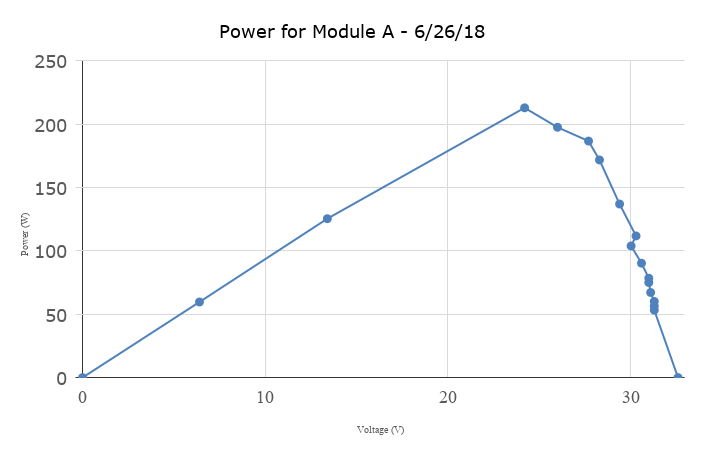
Graph the current against the voltage and the power against the voltage


Discussion
The module PMAX is the maximum in the power column, which is 213 W in the example above. The fill factor (FF) is calculated from the equation:
$$FF = \frac{P_{MAX}}{V_{OC} \times I_{SC}} $$
For the measurement above, ISC is the first line of the table (where V = 0) and equals 9.33 A and VOC is the last line of the table (where I = 0 ) and equals 32.6 V. The resulting FF is 0.70. Comparing the measured results to the specifications listed on the module label we have:
| Parameter | Specification | Measured |
|---|---|---|
| PMAX (W) | 295 | 213 |
| VOC (V) | 39.7 | 32.6 |
| ISC (A) | 9.61 | 9.33 |
| FF | 0.77 | 0.7 |
The previous page discusses the variation in VOC and ISC as a result of temperature and light intensity respectively. The measured FF was 10% lower than the specification, which is caused by the considerable scatter in the data. It is difficult to keep the module temperature and light intensity constant during the measurement. For instance, a person moving around the module is enough to alter the light on the module (even if they do not cast a shadow) by blocking some of the diffuse light.
Acknowledgment
The module measurement content was developed by the QESST Research Experience for Teachers (RET) program in Summer 2018. Team members (alphabetical order):
- Scott Currier (Fourth Grade Science Teacher, Highland Lakes School, Deer Valley Unified School District
- Lauren D'Amico (Science Teacher, Barcelona Middle School, Alhambra Elementary School District)
- Mark Calhoun (Physics Teacher, Camelback High School, Phoenix Union School District)
- Elliot Hall (Science Teacher, Barcelona Middle School, Alhambra School District)
- Alyssa Johnson (Akimel-A-al Middle School, Kyrene Elementary School District)
- Milt Johnson (Physics and Engineering Teacher, Bioscience High School, and Maricopa Community College Instructor)
- Leah Moran (Sonoran Trails Middle School, Cave Creek Unified School District)
- Meredith Morrissey (Science Teacher, Tempe High School, Tempe Unified School District)
- Myra Ramos (Math and Science Teacher, Alhambra Elementary School District)
- Tamara Waller (Fourth Grade Teacher, Alhambra Elementary School District)
- Allison Wolf (High School Science and Sustainability Teacher, Tempe High School, Tempe Unified School District)
