The amount of insolation acquired by the module during a certain time interval is one of the main preconditions for designing a PV system. It can be estimated by calculating the position of the Sun in the sky as well as the Air Mass value as shown on the page Calculation of Solar Insolation. Although this type of calculations gives a feeling of how much irradiation is available for a particular location and module orientation and how it is varying throughout the year, its output can't be used for the real system design because it doesn't include local weather variation which can dramatically change the radiation intensity. Another way of doing this is to use empirical radiation data collected by meteo station located at the place of interest. The obtained data sets including radiation and meteorological information for a typical year are available for the public and can be found in the form of xls spreadsheets.
The total amount of radiation received by the PV module, G, is composed of direct (beam), B, and diffuse, D, components.

In TMY file one can find both beam and diffuse components of radiation. Beam irradiance implies that it is received by the surface perpendicular to the Sun's rays. The beam component is actually calculated from diffuse and global horizontal irradiances, which are directly measured. For the systems with 2-axis trackers, adjusting themselves to face the sun in the same fashion as sunflowers do, the beam component comes directly from TMY (where it is called Direct Normal Irradiance, DNI). Unfortunately, the vast majority of PV systems are fixed in place and don't rotate. So they receive only a portion of direct sunlight which can be calculated having in mind the system location, module tilt and orientation 1:

where:
δ is the Declination Angle,
φ is the latitude of the location,
β is module tilt,
ψ is module azimuth (orientation measured from South to West),
and HRA is hour angle, discussed on the page Solar Time.
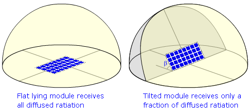
The calculation of diffuse component is more straight forward. From a simple model, assuming isotropic radiation from the whole sky dome, it follows that the module tilted by the angle β will receive just the proportional part of Diffuse Horizontal Irradiation, DHI, provided by TMY.


Although the simple model works pretty well for the desert locations it will introduce errors for the places with significant cloud coverage. For those parts of the Earth, the special models of the sky should be used to achieve higher accuracy. 2
TMY is measured on an hourly bases. The data is accumulated during the 60 min time intervals and is stored in a standardized form as shown on the following figure:

In the example above with a time stamp of 11:00 am, the data is collected over the period of 10 am to 11 am. The approximate average position of the sun over that period is 10:30 am or 30 minutes before the time stamp.
Combining the equations for the sun's position with those for the TMY data gives the hourly global irradiation on an arbitrary oriented and tilted surface, which can further be averaged or integrated through the required time interval. The contour plot, such as the one below, shows the irradiation on the modules versus module tilt and azimuth and can be used to calculate the yearly output of the module. For example, modules integrated into a vertical building wall facing East will generate around half the energy of modules that are South facing and tilted by the angle equal to the latitude.

The contour diagram of the global daily irradiation averaged through the year for Phoenix, AZ plotted for different module tilts and orientations. Note, that the number on the color bar corresponds to the peak sun hours, e.g. in Phoenix, if the module is facing South and tilted 40o, it will get about 6 peak sun hours of insolation during the day throughout the year. Click here to see the full size image. The actual data can also be obtained here.
Contour plots as well as data files for other locations throughout the US can be found below. It's interesting to note that the maximum incoming irradiation point is shifted from South to either East or West depending on the location. The reason for this behavior is the cloud coverage, which can appear mainly in the afternoon or in the morning during one of the seasons, causing the shift of the optimum orientation to the East or to the West correspondingly.
|
|
|
|
|
|
|---|---|---|---|---|
|
|
|
|
|
|
|
|
|
|
|
|
- 1. , “Handbook of Photovoltaic Science and Engineering”, p. 1117, 2003.
- 2. , “Modeling daylight availability and irradiance components from direct and global irradiance”, Solar Energy, vol. 44, pp. 271 - 289, 1990.
