At its simplest, the ideal diode derivation 1 results in the equation:
$$I = I_0 \exp{\left (\frac{qV}{k T} - 1 \right )}$$
Most diodes are not ideal and an 'ideality factor' is introduced to account for the departures from the ideal.
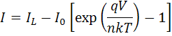
$$I = I_0 \exp{\left (\frac{qV}{n k T} - 1 \right )}$$
where n is the ideality factor and is one for an ideal diode. The ideality factor is also known as the "quality factor" 2 and also denoted with A or m
Departures from ideal happen for a variety of reasons. Some are parasitic and some are fundamental to the recombination process and diode operation. For example, the ideal diode derivation makes the assumption of low-level injection so that only one carrier limits the recombination. Other recombination mechanisms give a different ideality factor depending on the number of carriers that limit the recombination. The table below gives a simplified view of the recombination mechanisms and the resulting ideality factor.
| Recombination Type | Ideality factor | Description |
|---|---|---|
| Radiative (band to band) in low-level injection | 1 | Recombination limited by minority carriers. |
| Radiative (band to band) high-level injection | 2 | Recombination limited by both carrier types. |
| Defect-assisted (low level injection) | 1 | Recombination limited by minority carrier. |
| Defect-assisted (high level injection) | 2 | Recombination limited by both carrier types. |
| Auger | 2/3 | Two majority and one minority carriers required for recombination. |
| Depletion region (junction) | 2 | two carriers limit recombination. |
In practice, there is usually more than one recombination mechanism so it is unusual for the ideality factor to precisely match one of the values above. For example, a silicon solar cell might be expected to have an ideality factor of two at high-level injection. However, Auger injection will dominate above 1e16 where the ideality factor is 2/3.

The plot gives the IV curve of a diode in the darkalong with the ideality factor of a diode in the dark as a function of voltage
J0
The second term in the ideal diode equation is I0, which is described by slighly different terms including: "saturation reverse current", 1 "reverse saturation current", "saturation current" Green1982, Schroder2006 or "dark saturation current." It is the current that flows in reverse bias due to thermally generated carriers. It is termed a "saturation current" since the ideal diode equation quickly converges to -I0 for negative voltages. In practice, p-n junctions have imperfections so the current in reverse bias, while small, is larger than I0. The term "reverse saturation current" is even more confusing in photovoltaics since solar cells almost never operate in reverse bias and rarely in the dark. Given the confusing nature of the term an alternative term of "recombination parameter" was proposed but it does not seem to have caught on.
Despite its somwhat counterintuitive name, the reverse saturation current is central to the operation of photovoltaic devices.
The ideality factor is closely tied to the diode prefactor I0, or J0 when current densities are used. J0 is an expression of the recombination in the device. J0 will be a constant if the recombination parameters are constant. However, lifetime and carrier diffusivity vary with carrier concentration and so does I0
A solar cell is a large diode. The ideal diode
The ideality factor of a diode is a measure of how closely the diode follows the ideal diode equation. The derivation of the simple diode equation uses certain assumption about the cell. In practice, there are second order effects so that the diode does not follow the simple diode equation and the ideality factor provides a way of describing them.
Recombination mechanisms
The ideal diode equation assumes that all the recombination occurs via band to band or recombination via traps in the bulk areas from the device (i.e. not in the junction). Using that assumption the derivation produces the ideal diode equation below and the ideality factor, n, is equal to one.
However recombination does occur in other ways and in other areas of the device. These recombinations produce ideality factors that deviate from the ideal. Deriving the ideal diode equation by considering the number of carriers the need to come together during the process produces the results in the table below.
- 1. a. b. «The theory of p-n Junctions in semiconductors and p-n junction transistors», Bell System Technical Journal, vol. 28, n.º 3, pp. 435 - 489, 1949.
- 2. «The diode quality factor of solar cells under illumination», Journal of Physics D: Applied Physics, vol. 19, n.º 3, pp. 483 - 492, 1986.