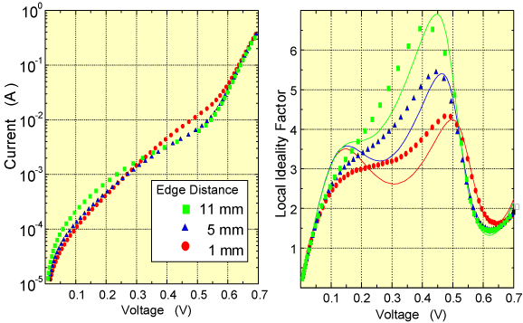
The ideality factor is derived from the slope of the dark-IV, Suns-Voc and occasionally the Light-IV curve.
The basic cell equation in the dark is:
$$I=I_{0}\left(\exp \left(\frac{q V}{n k T}\right)-1\right)$$
where I is the current through the diode, V is the voltage across the diode, I0 is the dark saturation current, n is the ideality factor and T is the temperature in kelvin. q and k are both constants. for V > 50 - 100 mV the -1 term can be ignored and so the above equation reduces to:
$$I=I_{0} \exp \left(\frac{q V}{n k T}\right)$$
taking the log of both sides of the equation gives:
$$\ln (I)=\ln\left(I_{0}\right)+\left(\frac{q V}{n k T}\right) V$$
When plotting the natural log of the current against the voltage, the slope gives q/nkT and the intercept gives ln(I0). In real cells the ideality factor depends on the voltage across the cell. The ideality factor can either be plotted as a function of voltage or it can be given as a single value. Since the ideality factor varies with voltage, if given as a single value the voltage range also needs to be given.
Deviations in the ideality factor from one indicate that either there are unusual recombination mechanisms taking place or that the recombination is changing in magnitude. Thus the ideality factor is a powerful tool for examining the recombination in a device. The measurement of I0 is only valid when the ideality factor is stable.
There are several practical problems when measuring ideality factors:
- At low voltages the shunt resistance (Rshunt)dominates the device performance and causes a large peak. It is usually not possible in practice to correct for the effects of Rshunt.
- At high voltages in a dark-IV curve the series resistance dominates and this causes a large peak in the ideality factor curve at high voltages. This can be alleviated by using the Suns-Voc curve that as noted earlier gives a curve the same as dark-IV but without the effects of series resistance.
- The ideality factor comes from the differential of a signal so it is very prone to noise. Noise problems are particularly problematical in Suns-Voc measurements. To reduces noise the slope is usually taken as a fit over several points.
- The effects of temperature are a problem particularly if the temperature change during the measurement.
The ideality factor animated graph below shows the effects on a dark IV curve. The curve without resistive effects is quite simple, at low voltages the ideality factor is two, at high voltages the ideality factor is one. Once the resistive effects are included the curve becomes quite complicated. The domination by Rshunt at low voltages means that the ideality factor at low voltages is not valid.
Local Ideality factor determined from the dark IV curve with and without the effects of parasitic resistance.

Dark IV measurements of buried contact cells and the extracted local ideality factor fits. The different curves are from varying the distance to the cell edge. The extracted ideality factors show that the unusual IV curves were due to the edge recombination (Picture redrawn from McIntosh 1.
- 1. , “The Influence of Edge Recombination on a Solar Cell’s IV Curve”, 16th European Photovoltaic Solar Energy Conference. 2000.
- Log in or register to post comments
- 1 comment(s)
