Simple Module Measurement with a Multimeter
Read the safety instructions before proceeding.
Measuring the full power output of a solar module requires a load. However, as a first step, we can use a simple multimeter to measure with no load to get the open current voltage, (VOC) and short circuit current (ISC). For large outdoor modules, any multimeter with a current scale that goes to 10 A (amps) and 50 V (Volts) will work. See below for the requirements on smaller modules. A thermal gun for measuring the temperature of the panel is useful on especially hot days. Choose a sunny day and point the module so it faces the sun. Make sure none of the module is shaded. Even shading part of one corner of the module will cause a dramatic loss in output.

In a typical multimeter, the negative terminal is the black lead and labeled COM. Plug the red lead into the V terminal for measuring voltage and the 10 A for large currents. If you are not familiar with a multimeter, here is a website that describes what a multimeter is and here is a link about how to use a multimeter. There is also a video on youtube.
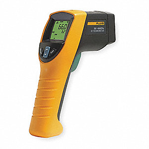
A temperature gun is only really needed on very hot days. The temperature should be measured on the back of the module as the reflection of the sun from the module will distort the reading. The material emissivity will also affect the reading so that point the sensor at a metal surface will give a different reading to back sheet even if they are at the same temperature. In most cases, the gun can be pointed anywhere on the back-sheet and give a reliable reading. However, a piece of black tape on the module can also be used to give a more reliable reading.
Measuring Voc
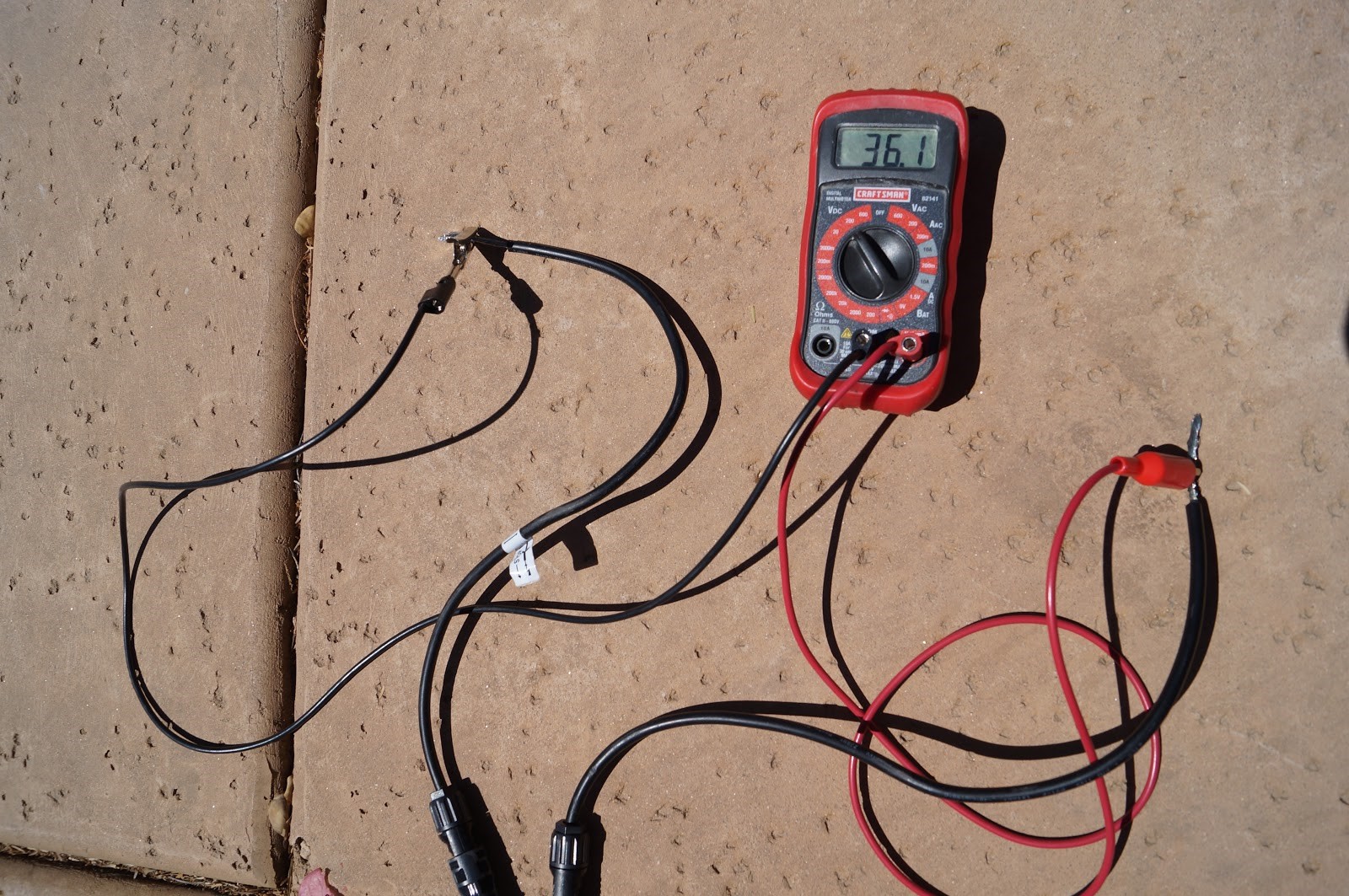
For VOC, set the multimeter to a DC voltage scale greater than the expected module voltage. Use the 200 V scale setting if unsure. Connect multimeter leads as shown below to the solar panel leads (power to power and ground to ground) and record the voltage. The VOC readings will decrease as the module heats up and this variation will be accounted for below. Record the temperature of the surface of the panel and the time of day in which your measurements were taken.

Measuring Isc
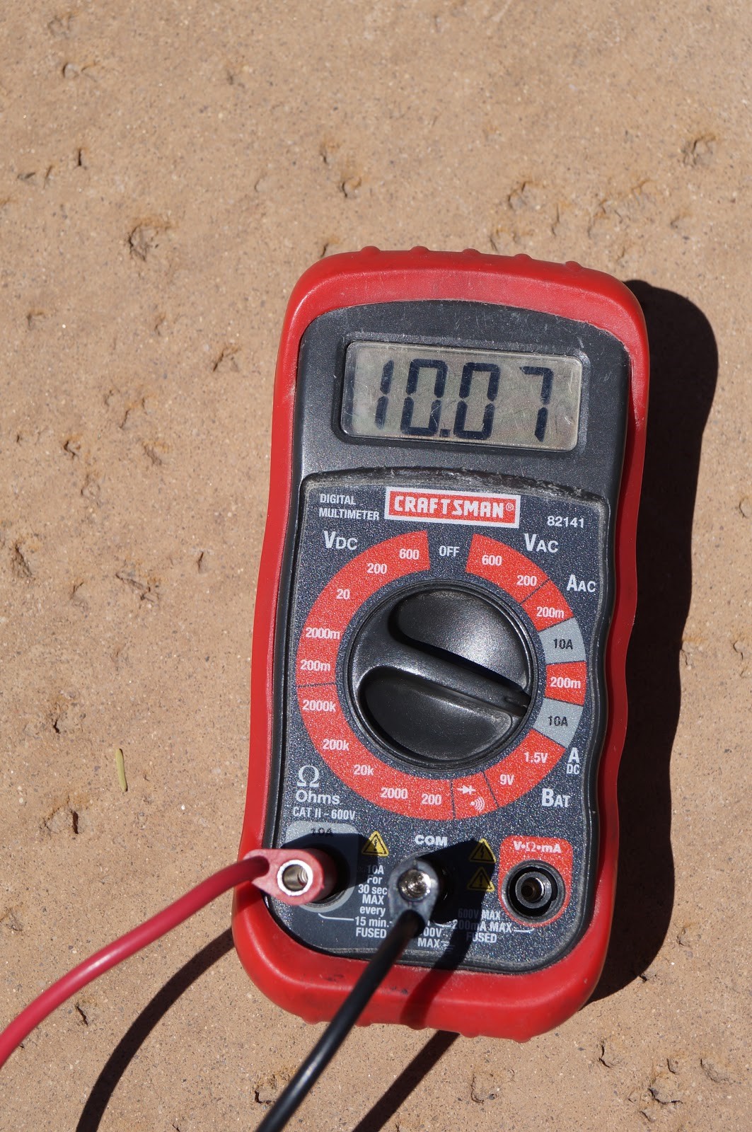
Disconnect the multimeter from the module before changing the setting. For ISC, set the multimeter to a DC current scale greater than the expected module current. Use the 10 A scale setting if unsure. Change the power (red) lead to the 10 A socket to prevent blowing the fuse inside the multimeter when taking your measurements. Connect the multimeter leads to the solar panel leads and record the voltage.
A video on how to measure current with a multimeter can be found on youtube.


Discussion
Multiplying the VOC and ISC together gives a rough estimate of the power. In this example case, the Voc equals 35.8 V, the current equals 10.07 and the product is 363.5 W. However, we must also take into account the fill factor. The maximum power (PMAX, or sometimes written MPP) equation is:
$$P_{MAX} = V_{OC} \times I_{SC} \times FF$$
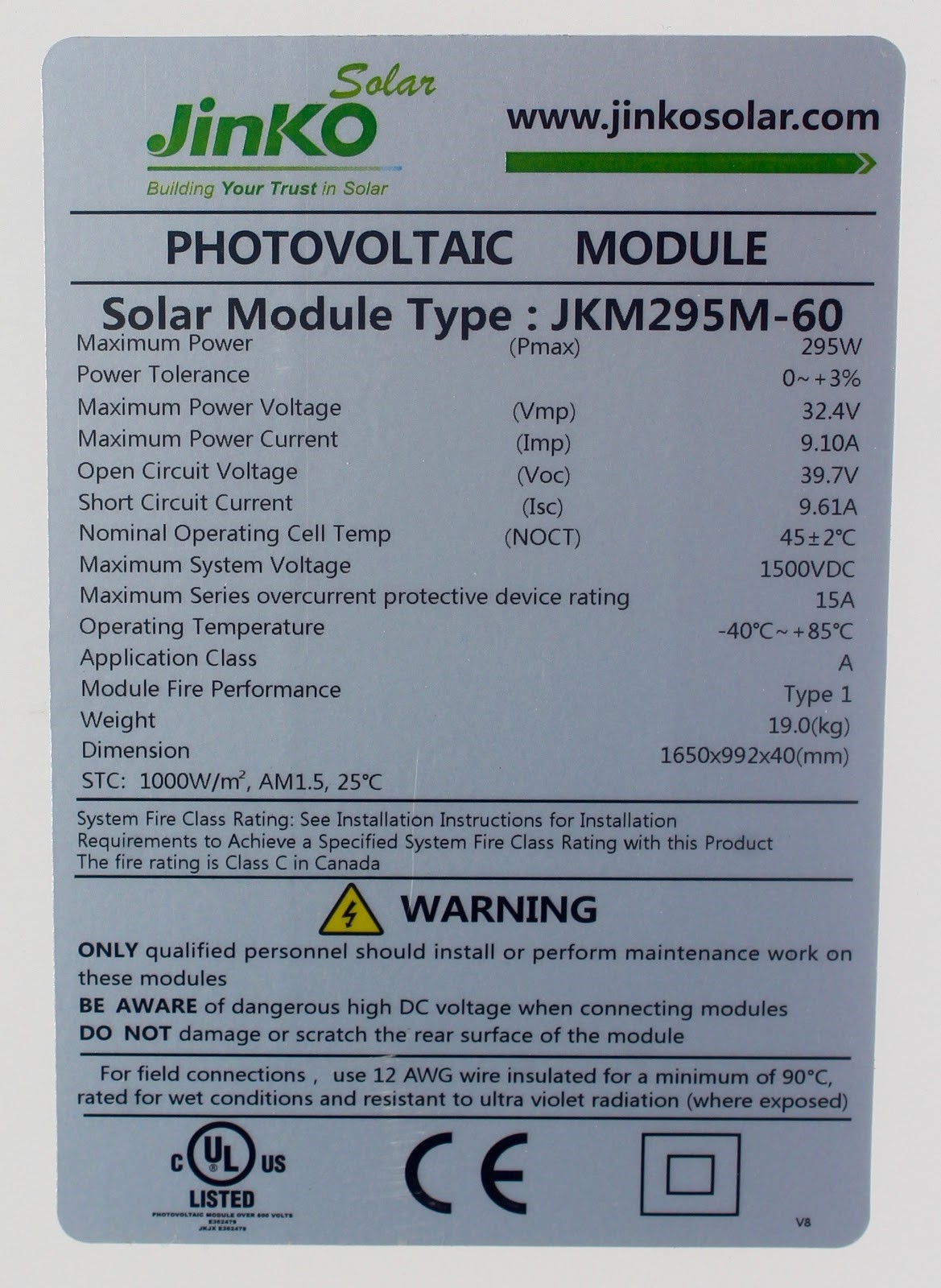
We cannot measure the fill factor without a load but it is typically around 0.7, so our PMAX is in this case 254.5 W. By determining the actual VOC, ISC, and estimated PMAX of the panel and comparing it to the rating of the module, one can quickly evaluate if a panel is performing near optimal. In the image below, a picture of this panel’s rating is included. Since the panel’s VOC and ISC are quite similar to the results determined in these measurements, it is likely that the panel is performing well.
Limitations
Although this is a quick and simple way to learn some information about the quality of a module, there are some distinct limitations. While this method shows that the solar module is functional and is putting out some amount of power, it fails to characterize the module’s efficiency or give any further specifications. This approach also fails to generate an IV curve, which means that while PMAX can be estimated, it cannot be determined exactly, or show how the panel might be affected by shunt or series resistance. For a better understanding of how the panel will operate with a load and to get these missing data points, refer to the next page. The measurement of VOC will be accurate to within 10% but ISC might be out by 50% or more.
Variations in VOC
The VOC is very dependent on the temperature and, to a lesser extent, on the sun’s intensity. Each cell in the module will fall by about 2.2 mV/°C. The standard for module measurement is 25 °C so we need to correct by 2.2 mV per cell for each degree above 25 °C. To correct for temperature in a silicon module use the following formula:
$$V_{corrected} = V_{measured} + 0.0022 \times N \times (T_{measured} - 25)$$
where Vmeasured is the voltage measured at VOC , Tmeasured is the module temperature in Celsius and N is the number of cells in the module.
Variation in ISC
ISC varies in proportion with the sun’s intensity, which varies with location and the time of day. Measuring the sun’s intensity is challenging and is covered on subsequent pages. A rough estimate is provided by measuring more than one module. If they all have about the same measured ISC then it is likely they are all functioning correctly. Measurement on a cloudy day will give about 10-20% of the rated output. Measurements in the shade or in a garage
Acknowledgment
The module measurement content was developed by the QESST Research Experience for Teachers (RET) program in Summer 2018. Team members (alphabetical order):
- Scott Currier (Fourth Grade Science Teacher, Highland Lakes School, Deer Valley Unified School District
- Lauren D'Amico (Science Teacher, Barcelona Middle School, Alhambra Elementary School District)
- Mark Calhoun (Physics Teacher, Camelback High School, Phoenix Union School District)
- Elliot Hall (Science Teacher, Barcelona Middle School, Alhambra School District)
- Alyssa Johnson (Akimel-A-al Middle School, Kyrene Elementary School District)
- Milt Johnson (Physics and Engineering Teacher, Bioscience High School, and Maricopa Community College Instructor)
- Leah Moran (Sonoran Trails Middle School, Cave Creek Unified School District)
- Meredith Morrissey (Science Teacher, Tempe High School, Tempe Unified School District)
- Myra Ramos (Math and Science Teacher, Alhambra Elementary School District)
- Tamara Waller (Fourth Grade Teacher, Alhambra Elementary School District)
- Allison Wolf (High School Science and Sustainability Teacher, Tempe High School, Tempe Unified School District)